

This is not a 5 minute job, so make sure you have the time to do it properly. There are some small and somewhat delicate pieces involved so patience is key.
Tools needed: Phillips screwdriver, small flathead screwdriver, needle nose pliers, 5mm Hex (allen), 3mm Hex (allen), torque wrench, Super Glue (or similar).
Step 1: The first thing that we need to do is remove the fuel tank. There is a detailed How To here.
http://www.yamaha-forum.net/forum/showthread.php?t=447
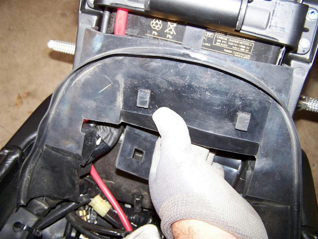
Step 2: Remove the rubber cover below the battery tray to access the Lean Angle Sensor.
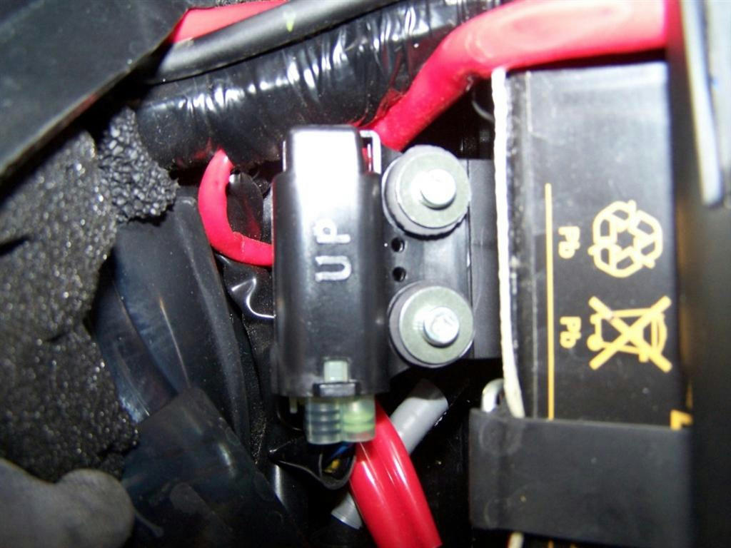
Step 3: Remove the 2 Lean Angle Sensor mounting bolts.
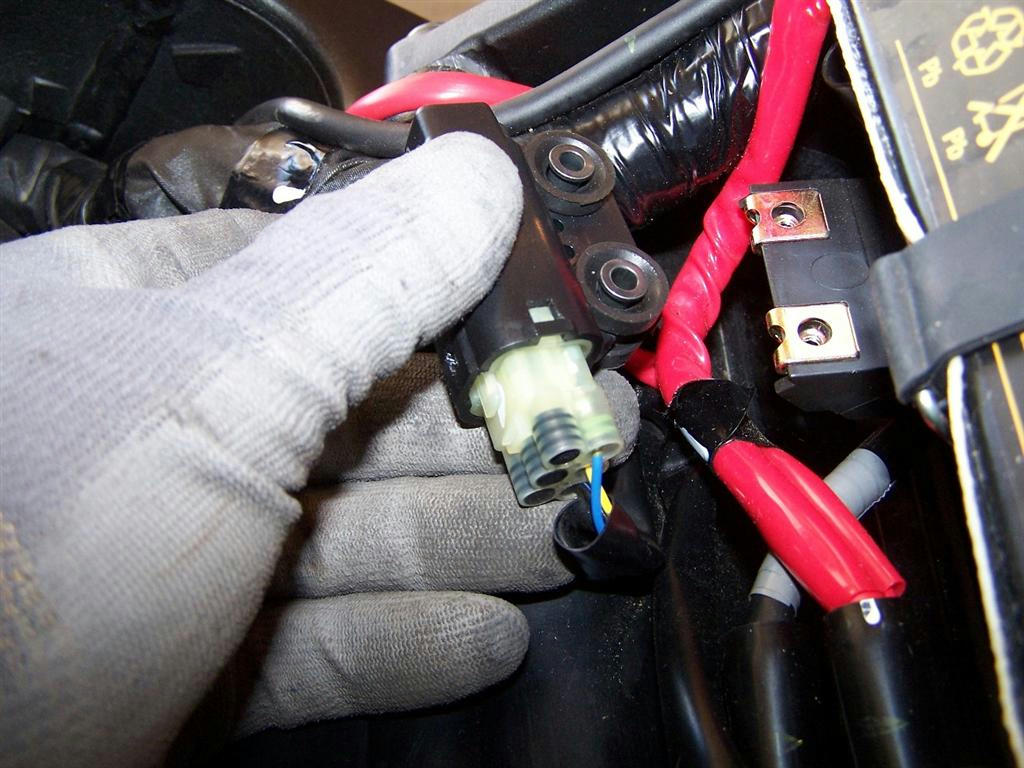
Step 4: Disconnect wiring.
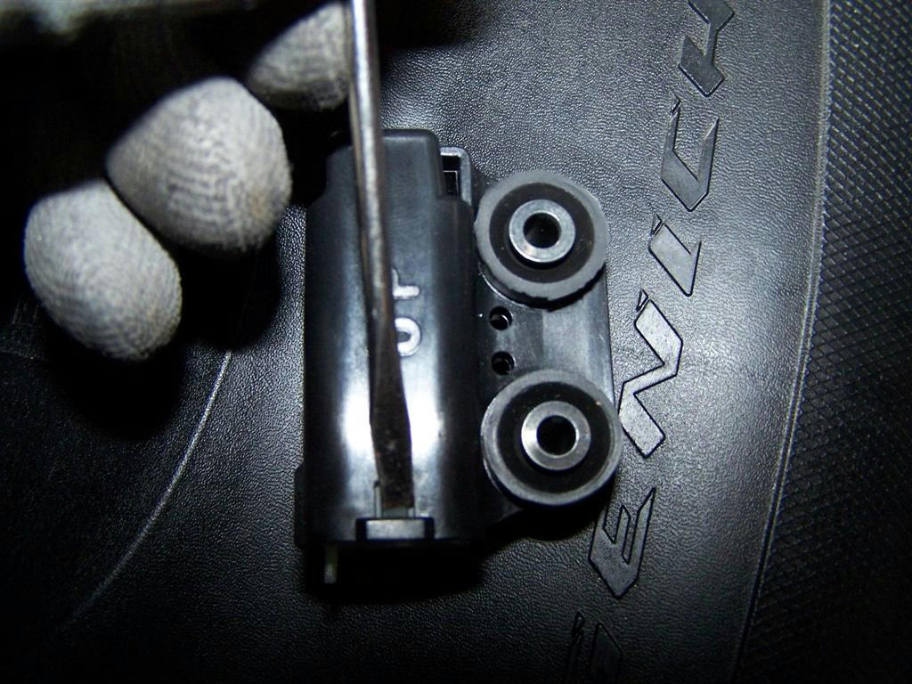
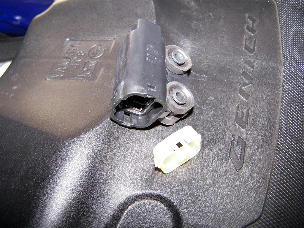
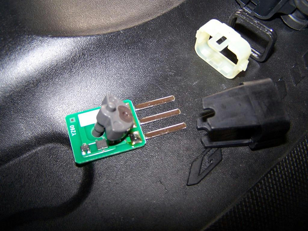
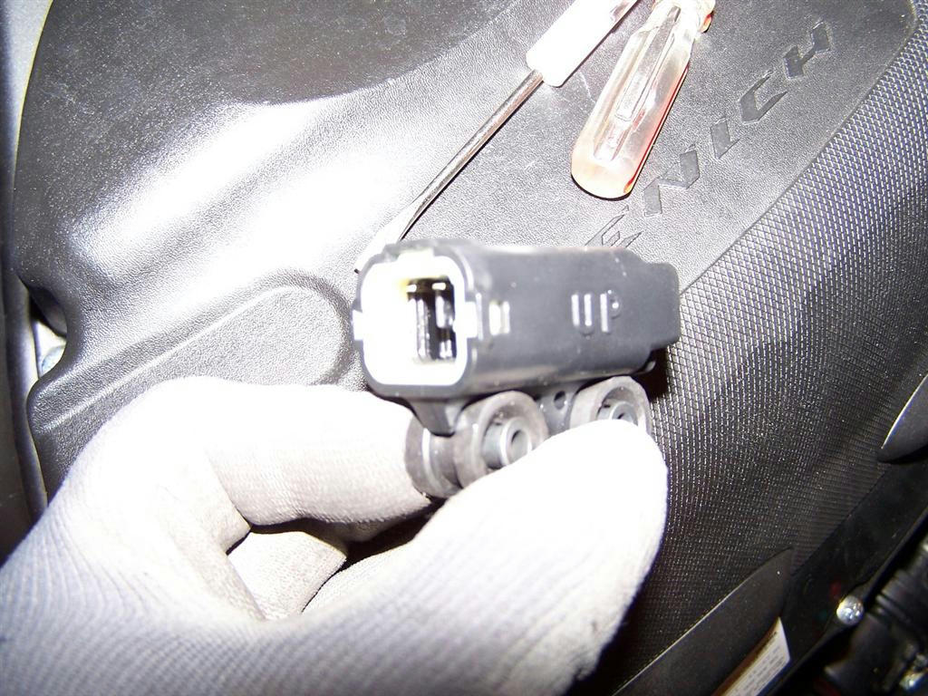
Step 5: Take a small flathead screwdriver and start working on pushing the white connecting spacer out of the box. There are 3 areas that you have to work on to get it out. One on UP side, one on the DOWN side. and one opposite the mounting bolts. There is also a Black gasket that can be removed next.
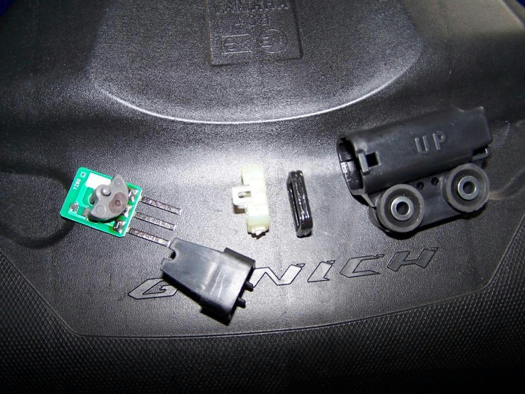
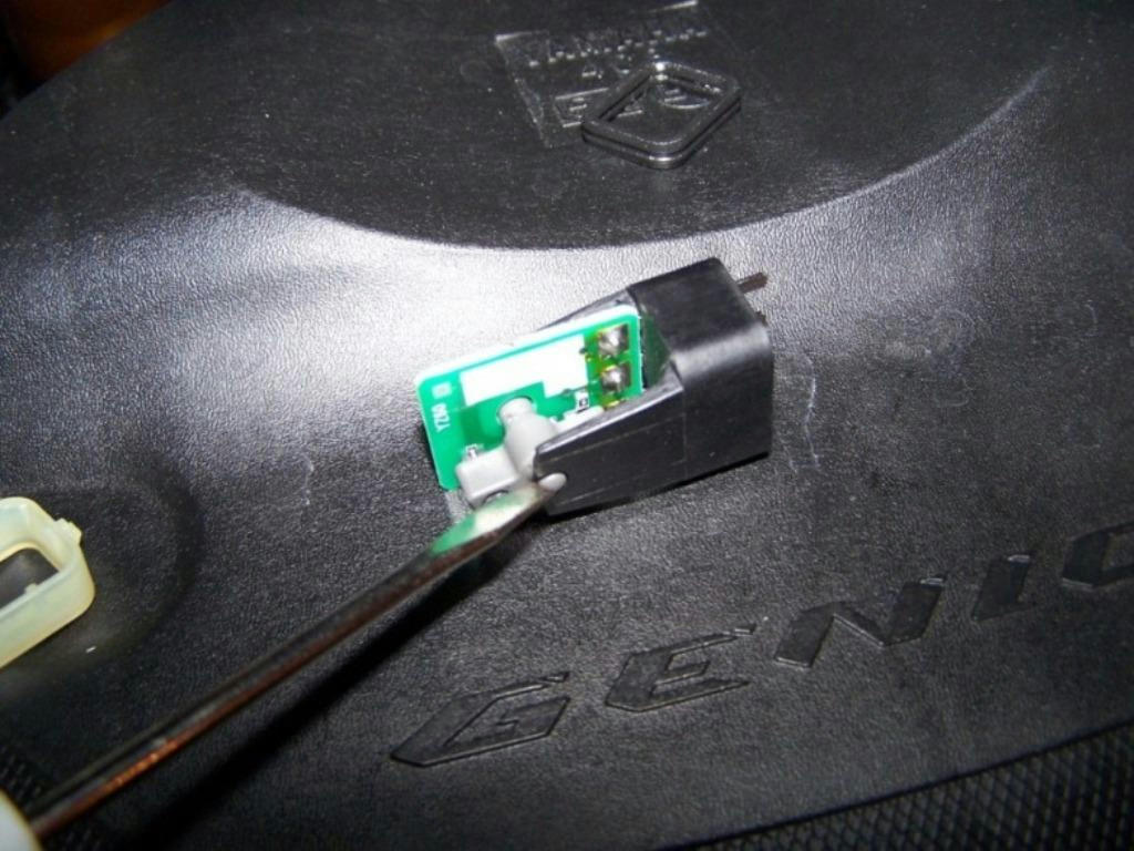
Step 6: Take needle nose pliers and lightly start pulling out the sensor by the metal connector tabs. Once you get it out far enough that you can pull it out by hand stop using the pliers. There are a couple of small pieces that are going to fall out, so you want to be able to hold on them. My pictures are fairly detailed, but you should still try to remember how everything comes apart.
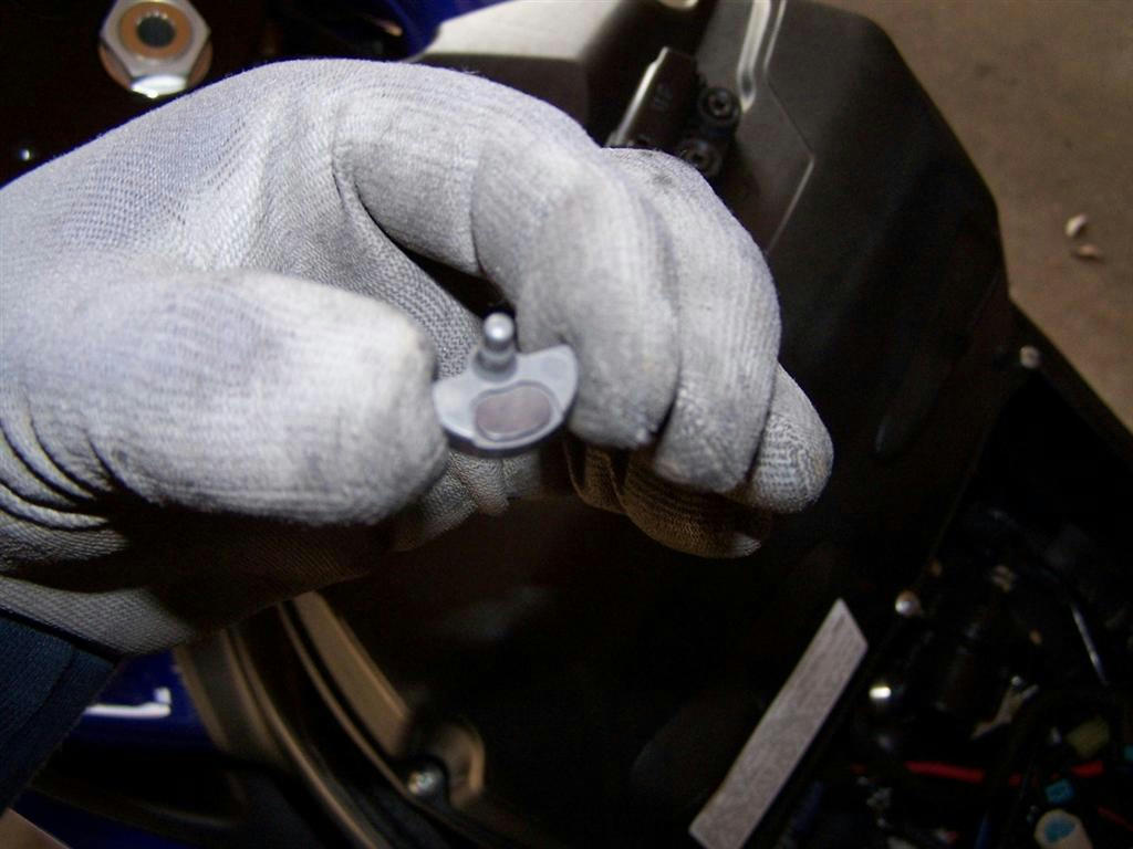
This is the part that activates the sensor. It has a small magnet/weight on the bottom side. This works similar to a pendulum.
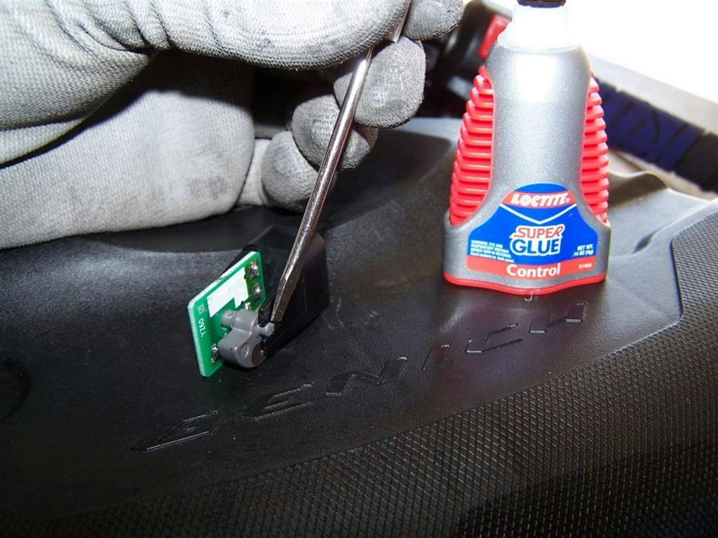
Step 7: We are going to partially reassemble the sensor. Assemble and disassemble the parts a couple of times so you feel comfortable are not fumbling around once you apply Supper Glue. The picture is with the unit in the UP position. The magnet/weight should be at the bottom/opposite the white part on the board.
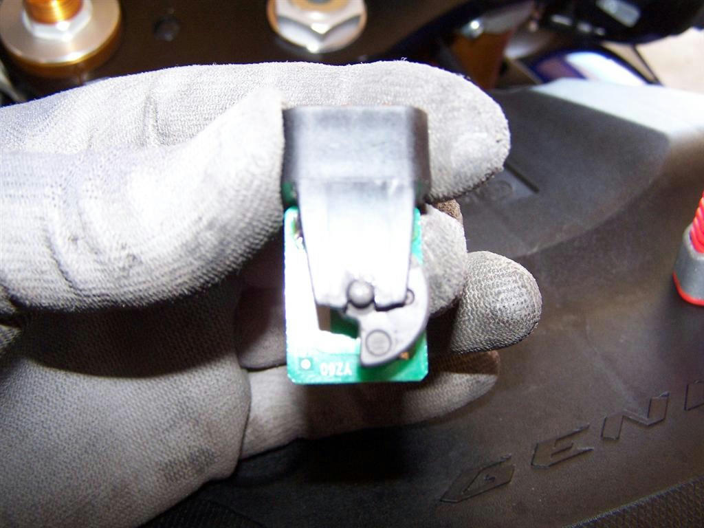
Step 8; Apply Super Glue on both of the U areas & assemble circuit board and pendulum. Let glue set for 5 minutes. It should look just like this picture when assembled.
You should now be able to turn the unit to any angle and the pendulum does not move. You now have a disabled Lean Angle Sensor.
Step 9: Reassemble the other pieces of the sensor.
Go back to Step 4 and work your way back to Step 1.
Ride safe.
Tools needed: Phillips screwdriver, small flathead screwdriver, needle nose pliers, 5mm Hex (allen), 3mm Hex (allen), torque wrench, Super Glue (or similar).
Step 1: The first thing that we need to do is remove the fuel tank. There is a detailed How To here.
http://www.yamaha-forum.net/forum/showthread.php?t=447
Step 2: Remove the rubber cover below the battery tray to access the Lean Angle Sensor.
Step 3: Remove the 2 Lean Angle Sensor mounting bolts.
Step 4: Disconnect wiring.
Step 5: Take a small flathead screwdriver and start working on pushing the white connecting spacer out of the box. There are 3 areas that you have to work on to get it out. One on UP side, one on the DOWN side. and one opposite the mounting bolts. There is also a Black gasket that can be removed next.
Step 6: Take needle nose pliers and lightly start pulling out the sensor by the metal connector tabs. Once you get it out far enough that you can pull it out by hand stop using the pliers. There are a couple of small pieces that are going to fall out, so you want to be able to hold on them. My pictures are fairly detailed, but you should still try to remember how everything comes apart.
This is the part that activates the sensor. It has a small magnet/weight on the bottom side. This works similar to a pendulum.
Step 7: We are going to partially reassemble the sensor. Assemble and disassemble the parts a couple of times so you feel comfortable are not fumbling around once you apply Supper Glue. The picture is with the unit in the UP position. The magnet/weight should be at the bottom/opposite the white part on the board.
Step 8; Apply Super Glue on both of the U areas & assemble circuit board and pendulum. Let glue set for 5 minutes. It should look just like this picture when assembled.
You should now be able to turn the unit to any angle and the pendulum does not move. You now have a disabled Lean Angle Sensor.
Step 9: Reassemble the other pieces of the sensor.
Go back to Step 4 and work your way back to Step 1.
Ride safe.
") I hear he's a great one too...
I hear he's a great one too... 


